
GPU Cluster Failure Domain Planning Across Multi-Rack Workloads
When enterprise organizations scale artificial intelligence infrastructure from a few isolated GPU servers to multi-megawatt computing superclusters, the primary architectural challenge shifts from maximizing peak raw throughput to containing the blast radius of inevitable hardware failures. In a cluster containing hundreds of high-density GPU nodes, thousands of optical transceivers, and complex liquid cooling distribution loops, hardware faults are statistical certainties rather than rare anomalies. If infrastructure components are tightly coupled without rigorous physical and logical failure boundaries, a localized fault—such as a tripped branch circuit breaker, a failing top-of-rack leaf switch, or a locked storage controller—can propagate into a catastrophic cluster-wide outage that terminates multi-week training campaigns. Comprehensive GPU cluster failure domain planning establishes isolated operational zones that contain hardware faults and maximize overall cluster availability.
Deconstructing Physical and Logical Failure Domains in AI Clusters
Architecting resilient AI infrastructure requires identifying and decoupling four interrelated failure domain layers:
- Electrical and Power Distribution Domains: Modern 8-GPU servers consume between 10kW and 12kW per chassis, with high-density racks drawing 40kW to 100kW+. An electrical failure domain encompasses the equipment supported by a common Power Distribution Unit (PDU), Uninterruptible Power Supply (UPS), or branch circuit. Sizing failure domains requires ensuring that a PDU trip impacts only a predictable subset of nodes (e.g., maximum 1 to 2 racks) rather than an entire computing row.
- Network Interconnect and Leaf-Spine Planes: In large-scale non-blocking 800G RoCE v2 or InfiniBand fabrics, failure domains align with switch hierarchy. A leaf switch failure domain contains all compute nodes dual-homed to that specific top-of-rack switch pair. A spine failure domain encompasses a complete network rail or plane. If network planes are improperly cross-connected, a routing loop in one rail can degrade the entire cluster.
- Parallel Storage Controller and Target Zones: High-performance NVMe-oF parallel storage systems distribute data across multiple storage targets. Sizing storage failure domains requires isolating metadata servers (MDS) and object storage targets (OST) across distinct physical chassis, ensuring that single-chassis power or controller faults do not render training datasets inaccessible.
- Cooling Loop and Coolant Distribution Units (CDUs): In Direct-to-Chip liquid-cooled environments, a CDU failure domain includes all server cold plates connected to a single secondary fluid loop. N+1 redundant pumps and automated manifold isolation valves are mandatory to prevent localized coolant leaks from taking down multiple compute rows.
Principles of Resilient Failure Domain Architecture
Infrastructure architects enforce four core design guidelines to eliminate systemic single points of failure:
- Decoupled Multi-Rail Network Topologies: Deploy rail-aligned network architectures where each GPU in an 8-GPU server connects to an independent, physically isolated spine network rail. If a spine switch or optical link fails in Rail 3, Rails 0 through 2 and 4 through 7 continue operating at full bandwidth, allowing training frameworks with adaptive routing to maintain computation without crashing.
- Topology-Aware Workload Scheduling (Slurm / Kubernetes): Orchestration engines must be explicitly configured with physical cluster topology maps. Schedulers place tightly coupled distributed training jobs (which rely heavily on high-speed NVLink and low-latency leaf switches) within the smallest possible failure domain (e.g., within a single rack or leaf switch pair), while distributing independent batch inference jobs across multiple domains.
- Independent Out-of-Band Management Infrastructure: Baseboard Management Controllers (BMC/IPMI), telemetry loggers, and cluster control planes must operate on separate physical switches and power circuits. A complete compute fabric crash must never blind operations teams to node telemetry or prevent remote IPMI power-cycling.
- Automated Blast Radius Cordoning: Monitoring systems must integrate with cluster schedulers. When telemetry detects anomalous voltage fluctuations or optical bit error surges within a specific rack, the scheduler cordons the entire failure domain, drains active jobs to healthy standby instances, and prevents new workloads from scheduling on the impacted hardware.
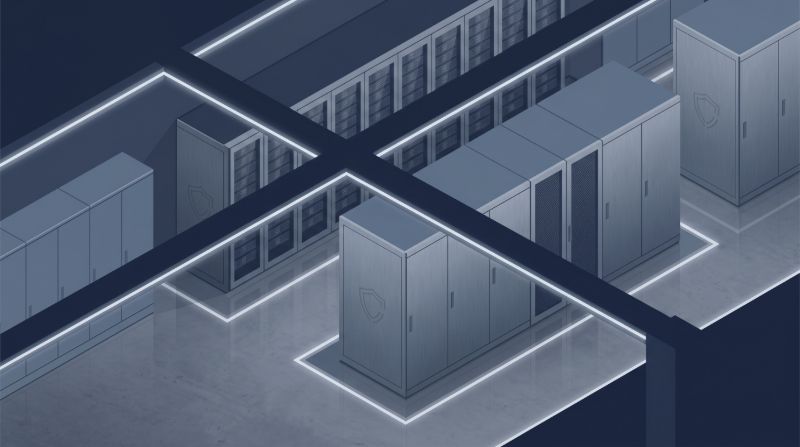
With OneSource Cloud's dedicated AI infrastructure, enterprises deploy mission-critical AI workloads onto infrastructure engineered with strict failure domain boundaries. OneSource provides single-tenant bare-metal clusters featuring 2N power redundancy, multi-rail 800Gbps RoCE v2 networks, and distributed NVMe-oF storage fabrics, fully orchestrated by the OnePlus™ AI Platform for automated fault isolation and zero downtime.
Comparative Failure Domain Architecture Matrix
The following technical matrix evaluates failure domain characteristics across unmanaged commodity clusters, multi-tenant cloud environments, and OneSource Cloud's engineered bare-metal AI infrastructure:
| Failure Domain Dimension | Unmanaged Commodity Cluster | Multi-Tenant Virtualized Cloud | OneSource Dedicated AI Infrastructure |
|---|---|---|---|
| Power Redundancy Architecture | Single feed or basic 1N PDU | Shared multi-tenant data center | True 2N Dual A/B Utility & UPS Feeds |
| Leaf Switch Failure Blast Radius | Entire rack (8 to 16 nodes lost) | Variable VM hypervisor outage | Sub-second failover via dual-homed RoCE v2 |
| Spine Fabric Fault Isolation | Single converged network plane | Opaque multi-tenant routing | Physically isolated multi-rail non-blocking fabric |
| Storage Controller Zone Redundancy | Single dual-controller head | Shared cloud storage regional quotas | Distributed all-flash NVMe-oF parallel targets |
| Liquid Cooling Fault Containment | Facility-wide shared chiller loop | Standard data center air cooling | Isolated rack manifolds with automated leak shutoff |
| Orchestration Topology Awareness | Flat scheduling (High blast radius) | Availability Zone level only | Rack-and-leaf topology-aware Slurm/K8s scheduling |
This comparison confirms that disciplined failure domain planning is essential for isolating physical hardware faults and sustaining high availability in AI computing.
Failure Domain Planning Implementation Checklist
Before commissioning a multi-rack GPU supercomputing facility, infrastructure engineers must verify five critical fault-isolation controls:
- Execute True Dual-Feed Power Loss Drills: De-energize primary "A" side power distribution panels under 100% compute load, verifying that secondary "B" feeds sustain all servers without voltage dips or node restarts.
- Map Topology Hierarchies in Cluster Schedulers: Define explicit rack, leaf, and switch hierarchy blocks in
slurm.confor Kubernetes topology plugins to ensure locality-aware job allocation. - Validate Multi-Rail Network Rail Independence: Sever connectivity to a single spine rail switch and confirm that inter-GPU collective communications continue uninterrupted across remaining rails.
- Audit Physical Liquid Cooling Manifold Isolation: Verify that each rack manifold features automated isolation valves capable of halting fluid flow within 200 milliseconds of leak detection.
- Establish Pre-Warmed Standby Capacity per Zone: Maintain 5% to 10% unallocated standby compute capacity distributed evenly across failure domains for instantaneous job migration.
FAQ
What is the primary benefit of failure domain planning in large-scale GPU clusters?
Failure domain planning isolates physical electrical, network, and storage components into decoupled zones, ensuring that a localized hardware failure (such as a blown breaker or dead leaf switch) impacts only a minor subset of nodes rather than halting the entire cluster.
How does OneSource Cloud prevent cascading hardware failures in enterprise AI clusters?
OneSource Cloud engineers its dedicated bare-metal infrastructure with strict 2N power redundancy, multi-rail non-blocking 800Gbps RoCE v2 networks, and distributed NVMe-oF storage fabrics, orchestrated by the OnePlus™ Platform to automatically isolate faults without interrupting active training runs.
Related Articles
Recommended Reading
-
How Paged Attention Manages Inference KV Cache
-
Google Cloud GPU Pricing: What Enterprise AI Teams Should Evaluate Before Provisioning
-
Paperspace Pricing 2026: GPU Cost Breakdown
-
AI Infrastructure Costs: Controlling Enterprise GPU Spending
-
CoreWeave Enterprise GPU Cloud: Evaluation for AI Teams
-
CoreWeave vs Lambda Labs: GPU Cloud Provider Comparison
-
AWS GPU Pricing: Instance Types, Cost Structure & Alternatives Guide
-
CoreWeave Alternatives: Compare GPU Clouds
latest articles
-
On-Premise AI Infrastructure vs Colocation vs Hosted Cloud
-
AI Orchestration Platform: How It Works on a Private GPU Cluster
-
Best GPU Cloud Hosting Providers: Why Rankings Differ and How to Build Yours
-
The Four Categories of Cloud Platforms for AI Workloads
-
RunPod Compared: How It Stacks Up Against Other AI Cloud Providers
-
Sovereign AI Cloud: Data Control for U.S. Enterprises
-
How to Choose a HIPAA-Compliant AI Infrastructure Provider
-
How to Build Private AI Infrastructure From Sizing to Operations
-
Lambda Labs Alternatives for Teams Outgrowing GPU Rental
-
GPU Cloud Computing: Comparing Bare Metal vs Virtualized vs Serverless Providers