
Sizing GPU Rack Power Density: A Step-by-Step Method for AI Clusters
GPU rack power density is the total power draw of everything in a rack — servers, GPUs, networking, and overhead — divided by the rack's footprint, and calculating it correctly is what determines whether a facility can actually support an AI cluster or will trip breakers and overheat instead. Teams that size GPU count without calculating rack density discover the facility limit only when the cluster fails to run at full load.
For anyone planning an AI cluster, power density is the constraint that most often caps what a facility can host. Modern GPU servers draw far more power than general-purpose servers, and a rack that comfortably held traditional compute can overload when filled with GPUs. Calculating density before deployment is the difference between a cluster that runs and one that cannot be fully powered or cooled.
This guide walks through the power density calculation step by step: the inputs, the math, the overhead factors teams forget, and how to match cooling and facility power to the result. It treats density as a planning discipline, because that is what prevents expensive surprises after hardware arrives.
Why Power Density Is the Binding Constraint for AI Clusters
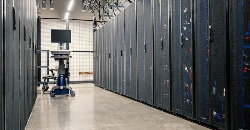
AI clusters concentrate power draw far more than traditional data center workloads. A single GPU server can draw several kilowatts, and a full rack of GPU servers can draw tens of kilowatts, which exceeds the per-rack power and cooling capacity of most legacy facilities. The result is that a facility's per-rack power and cooling limits, not its total square footage, determine how many GPUs it can host. Calculating density tells you that limit before you commit to hardware.
This matters because exceeding the limit has real consequences. Overloading a power circuit trips breakers and takes the rack offline. Exceeding cooling capacity causes thermal throttling, which silently slows training and inference, or triggers automatic shutdowns that protect hardware but interrupt workloads. Both failures are expensive and both are avoidable with density planning done before deployment.
Step 1: Gather the Per-Server Power Inputs
Start with the power draw of each component in a server, because the server is the unit that populates a rack. The inputs are the GPU power draw (the TDP or typical draw of each GPU at full load), the CPU power draw, the memory and motherboard draw, the network adapter draw (which matters for GPU servers with high-bandwidth NICs), and the storage draw. Sum these to get the server's theoretical draw, then apply a realistic load factor, since real workloads rarely sustain 100% of every component simultaneously but can come close during sustained training.
Use realistic peak draw, not nameplate ratings. Nameplate ratings are conservative maximums that overstate typical draw, while idle ratings understate peak. For AI workloads, assume sustained near-peak draw during training, because training loads GPUs, CPUs, memory, and networking together for long periods. Planning for idle or average draw is how teams end up with overloaded circuits when a real training run starts.
Per-server power inputs
| Component | Typical consideration |
|---|---|
| GPUs | TDP or sustained full-load draw per GPU, times the count per server |
| CPU | TDP of the server CPU(s) |
| Memory and motherboard | Draw of DIMMs, baseboard, management |
| Network adapters | High-bandwidth NICs draw meaningful power |
| Storage | NVMe and boot drives under load |
| Load factor | Realistic sustained draw during AI workloads, not nameplate or idle |
Step 2: Add Rack-Level Overhead
Server power is only part of rack draw. Add the overhead that teams forget but that consumes real power: the networking switches (especially high-radix GPU fabric switches, which draw substantially), the rack-level management and out-of-band systems, and any in-rack cooling or power distribution losses. These overheads can add a meaningful percentage to the rack total, and omitting them is a common source of under-provisioning.
Also account for power conversion losses in the power chain, from the facility feed through the PDU to the servers. Conversion is not 100% efficient, so the facility must supply more power than the servers consume. The exact loss depends on the power chain design, but ignoring it means the facility is sized to the servers' draw rather than to the draw plus losses, which again leads to overload.
Step 3: Compute Rack Power and Density
Sum the per-server draw across all servers in the rack, add the rack-level overhead and conversion losses, and the result is the rack's total power draw in kilowatts. Divide by the rack's footprint (typically a standard rack unit of floor space) to get power density, often expressed as kW per rack. This number is what you compare against the facility's per-rack power and cooling capacity.
Calculate both average and peak density. Average density matters for facility total capacity and cost, but peak density is what trips breakers and overwhelms cooling. A rack whose average draw fits the facility but whose peak draw exceeds circuit limits will still fail. Plan for peak, and confirm the facility's power and cooling can sustain it, not just the average. A dedicated infrastructure provider that has already validated high-density GPU racks can confirm these numbers against real deployment rather than estimates.
Step 4: Match Cooling to the Density
Power in becomes heat out, so cooling capacity must match the rack's power draw. Traditional data center cooling, designed for lower-density racks, often cannot remove the heat a high-density GPU rack generates, which causes thermal throttling or shutdown. Match the cooling method to the density: perimeter air cooling may suffice for moderate density, but high-density GPU racks typically need row-based or in-rack cooling, and the highest densities may require liquid cooling.
Cooling planning must account for peak density, not average, because cooling that handles average draw will fail during peak training load exactly when the cluster is doing its most valuable work. Also consider the cooling system's own power draw, which adds to facility power demand and can itself be a constraint. For teams without facility engineering depth, providers that operate high-density AI infrastructure handle this matching, which is why many teams choose managed high-density hosting rather than retrofitting their own facility.
Step 5: Validate Facility Power and Cooling Limits
The final step is comparing the calculated density against the facility's actual per-rack power and cooling capacity. Confirm the circuit and PDU capacity per rack, the total facility power available (since many GPU racks together can exceed total facility feed), the cooling capacity per rack and total, and the facility's power and cooling redundancy for the target density. A facility that meets one limit but not another cannot host the planned cluster at full density.
This validation often reveals that a facility cannot host as many GPUs as the team planned, which is exactly the point of the calculation. Discovering this before deployment lets the team adjust — reduce density, upgrade the facility, or choose a provider with higher-density capacity — rather than discovering it after hardware arrives and cannot be fully powered. The calculation is valuable precisely because it surfaces the binding constraint early.
FAQ
How much power does an AI GPU rack use?
It depends on the GPU type, server density, and workload, but a fully populated rack of modern GPU servers commonly draws tens of kilowatts, far more than a traditional server rack. Calculate the total by summing the per-server draw (GPUs, CPU, memory, networking, storage) at realistic sustained load, adding rack overhead and conversion losses, then compare against the facility's per-rack power capacity. Use realistic peak draw during training, not idle or nameplate ratings.
How do I calculate GPU rack power density?
Gather each server's component draw (GPU TDP times count, CPU, memory, networking, storage) at realistic sustained load, sum across all servers in the rack, add rack-level overhead like switches and management, add power conversion losses, and divide by the rack footprint to get kW per rack. Calculate both average and peak density, and plan for peak since that is what trips breakers and overwhelms cooling.
What cooling do high-density GPU racks need?
Cooling must match the rack's power draw, since power in becomes heat out. Traditional perimeter air cooling often cannot handle high-density GPU racks, which typically need row-based or in-rack cooling, and the highest densities may require liquid cooling. Plan cooling for peak density, not average, because cooling sized for average draw fails during peak training load exactly when the cluster is most valuable.
How do I avoid overloading facility power with GPU racks?
Calculate each rack's peak power density before deployment, including server draw, overhead, and conversion losses, and compare it against the facility's per-rack circuit and PDU capacity. Also confirm total facility power and cooling against the aggregate of all planned racks, since many high-density racks together can exceed the total facility feed. Validating before deployment lets you adjust density or facility rather than discovering the limit when breakers trip.
Should I plan for average or peak rack power?
Plan for peak. Average density matters for total facility capacity and cost, but peak density is what trips circuits and overwhelms cooling. AI training loads GPUs, CPUs, memory, and networking together for long periods, sustaining near-peak draw, so a rack whose average fits the facility but whose peak exceeds limits will still fail during real workloads. Size power and cooling for peak and you cover both.
Summary
Calculating GPU rack power density means summing each server's realistic sustained draw (GPUs, CPU, memory, networking, storage), adding rack overhead and conversion losses, and dividing by rack footprint to get kW per rack. The binding constraint for AI clusters is per-rack power and cooling capacity, not total square footage, and exceeding it trips breakers and overwhelms cooling. Plan for peak density, not average, because peak is what fails during real training. Match cooling to the density, validate the facility's per-rack and total limits before deployment, and adjust density, facility, or provider when the calculation surfaces a constraint. Teams that calculate density early avoid the expensive surprise of hardware that cannot be fully powered or cooled.
For teams that want high-density GPU hosting without retrofitting their own facility, dedicated AI infrastructure operated at validated high density provides the power and cooling capacity modern GPU racks require.
Related Articles
Recommended Reading
-
Google Cloud GPU Pricing: What Enterprise AI Teams Should Evaluate Before Provisioning
-
Paperspace Pricing 2026: GPU Cost Breakdown
-
CoreWeave Enterprise GPU Cloud: Evaluation for AI Teams
-
AI Infrastructure Costs: Controlling Enterprise GPU Spending
-
CoreWeave vs Lambda Labs: GPU Cloud Provider Comparison
latest articles
-
Open-Source LLM Deployment: Requirements and Real Cost Breakdown
-
AI Search Assistants Under Data Residency: Architectures and Evidence
-
LLM Inference GPUs Compared: A100, H100, H200, or B200 for Production
-
LLM Deployment Best Practices: An Enterprise Stage-by-Stage Checklist
-
HIPAA Patient Scheduling AI: Controls, Consent, and Evidence
-
Cloud-Agnostic LLM Deployment: Architecture Principles Against Lock-In
-
HIPAA-Compliant AI Tools for Healthcare: Categories and Evaluation
-
Batch vs Real-Time LLM Inference: Cost, Latency, and Fit
-
Model Deployment Strategies Compared: Canary, Blue-Green, Shadow, Rolling
-
GPU Rental vs Owning: Cost, Commitment, and When to Buy